|
JOINT MEETING EUROPEAN FREQUENCY AND TIME
FORUM IEEE IFCS ONE GIGAHERTZ LOW PHASE NOISE OSCILLATOR FOR ON BOARD AVIONIC APPLICATIONS O. FRANQUET B. WOLCOFF
1-ABSTRACT The aim of this paper is the presentation of a low phase noise 1 GHz oscillator developed by A.R.Electronique for tactical on board avionic applications. The typically requested performances for UHF oscillators in radar applications are :
To reach this level of performances, A.R.Electronique has developed a design based on the use of a VHF AT CUT CRYSTAL with optimized low g sensitivity parameters. The XTAL oscillator frequency is multiplied and filtered by a specific dielectric filter to obtain the UHF signal. Finally, an amplifier match the signal at standard power level. After the description of the quartz optimization, its oscillator and the other parts of the electronic structure, we show experimental results obtained with this UHF oscillator such as :
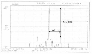
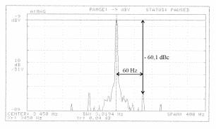
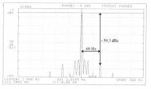
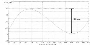
A discussion about the other interests of such a structure will conclude this paper. 2- UHF OSCILLATOR DESCRIPTION The design [fig.2-1] developed presents more than one interest. The use of quartz crystal with high quality factor allows us to obtain low phase noise oscillator. The frequency accuracy is better than +/-10ppm. The frequency deviation induced by temperature is small comparatively to other kind of resonators. Figure 2-1 : principle of the UHF oscillator 2-1- XTAL choice an optimization The heart of this structure is the quartz crystal, especially developed for this application. In order to minimize the effect of phase noise degradation due to the frequency multiplication ratio (20 Log (N)), we have chosen to design a quartz crystal oscillator with the highest possible frequency and compatible with the other characteristics. The frequency is around 200 MHz. In this case, the frequency multiplication ratio for a 1 GHz final signal is 5, that induce noise degradation of 14dB on phase spectrum. This resonator is able to resist to shocks (fire gun) and vibration profile specific to fighter airplanes. To reach these objectives, we have worked on the plate design and on a harded structure to mount the resonator. Dimensions of plate, structure and diameters of the electrodes are adjusted to obtain a 7th overtone AT CUT resonator with high surtension factor, typically > 70000. We also have not found significant dips (<10-7) on this resonator. Moreover, the relative thickness of this plate due to the 7th overtone eliminate the risk of acoustic effect on the XTAL that we can regularly observe for thin plate structures. The resonator is mounted in a T08, 4 points enclosure. The original mounting structure is optimized : - to minimize stress and strain on the plate in order to reduce g sensitivity coefficient in 3 axes. - to improve the mechanical behavior of the XTAL under vibration. The lower mechanical resonances of the structure are beyond 6 KHz. With this process, we have batch of resonators with an average g sensitivity < 5.10-10/g in the worst axis (Z axis, perpendicular to the plate). For example, fig. 2-2 shows the repartition of g sensitivity in a batch. Figure 2-2 : g sensitivity distribution in a batch The expected aging for these resonators is nearly 2ppm the first year and 1ppm after. Fig 2-3 a, b, c show the practical measurement of g sensitivity on these resonators. We use a sine excitation with a 60Hz modulation frequency, the excitation level is 3 g peak. G sensitivity coefficient k is given by : where :
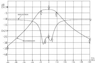
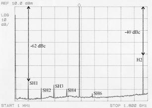
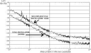
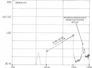
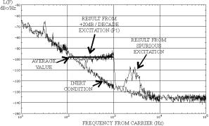
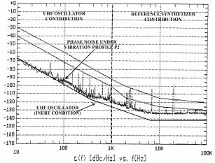
(a) : z axis : k ~ 1,0.10-10 / g (b) : y axis : k ~ 5.10-11 / g (c) : x axis : k ~ 5.10-11 / g Figure 2-3 a, b, c: g sensitivity measurement (#354 sample) The experimental set up is shown fig. 2-4, the UHF signal from DUT is mixed with a reference signal at F+ ~3KHz and send to the spectrum analyser to measure the modulation level at FM. Fig. 2-4 : experimental set-up 2-2- Electronic structure description 2-2-1- XTAL oscillator XTAL oscillator includes 3 parts : - oscillator circuit, - output amplifier, - circuit for supply regulation and ripple rejection. The oscillator is not ovenized and is able to work in a wide range of temperature [-55, +95]°C at ~ 200 MHz. A simple Colpitts structure is well adapted for working in this conditions and the frequency is also easily adjustable by external bias. A cascode amplifier provides a good isolation (~ 50dB) to minimize frequency pulling. The output HF level is adjusted to provide a full compatibility with the frequency multiplier input. In order to perform a good phase noise level even under a very noisily supply (white noise up to 2 MHz, 100mV peak to peak), a voltage regulator limits pushing effect and a specific ripple rejection circuit suppresses noise supply pollution. 2-2-2- Frequency multiplier and UHF filter For the multiplier the problem is that we are at the edge of two technologies ; RF frequencies with classical discrete components and Hyper frequencies with lines and specific microwave components. Some difficulties appear with the use of standard components. For instance, multiplication with several tuned stages requires very low value for inductances and many adjustments. It cant be an industrial solution. Moreover, in our case a times 5 multiplication ratio is not possible. A diode multiplier with gsm range components seems to be a good alternative. We are able to choose a times N multiplication ratio (odd or even). This multiplier (fig. 2-5) is simple and efficient and does not require any specific adjustment in production phase. Fig.2-5 : Multiplier synoptic This multiplier does not bring excess noise on the final phase spectrum (fig.3-2) In order to suppress all sub-harmonics (at N x FXTAL) from the comb generate by the diode multiplier, a selective dielectric filter is inserted at the output (fig.2-6). With this filter we ensure the objective of more than 60dBc rejection for spurious and sub-harmonics. Fig.2-6 : dielectric filter response Finally an integrated UHF amplifier gives a 10 dBm output power. Fig. 2-7 presents final output signal spectrum. Fig. 2-7 : output UHF signal 3- EXPERIMENTAL RESULTS 3-1- Thermal behavior Thermal behavior of UHF oscillator is led by XTAL behavior (fig. 3-1). The frequency drift with temperature with this AT cut is reduced to ~20ppm peak to peak without any dip in this wide range of temperature. Fig.3-1 : thermal behavior of the oscillator 3-2- Phase noise 3-2-1- Inert condition Fig. 3-2 : Phase noise The lower curve is phase noise at the output of XTAL oscillator. The upper curve is the noise at final output. No excess intrinsic noise from multiplier, filter or amplifier appears on final signal. We find again the ~14dB noise degradation induced by the multiplication. 3-2-2- Phase noise under vibration Another evaluation of g sensitivity consists in a wide range excitation noise with a slope + 20dB / decade (fig. 3-3). The effect on phase noise curve is a floor like on fig. 3-4. This method is more accurate than sine method. g sensitivity coefficient is given by : Fig. 3-3 : excitation noise profile Fig. 3-3 profile is the control accelerometer response placed near the oscillator, then we can notice typical spurious resonance from excitation set-up for F>2KHz. Fig. 3-4 : phase noise under excitation profile P1 (#354 sample) Average value on fig. 3-4 allow us to calculate g sensitivity using the previous formula. In this case k » 1,1.10-10 /g. We find again (at 10 percent) the result obtained with sine method (fig. 2-3 a). The applied vibration spectrum (fig. 3-5) is a real avionic profile. The excitation is oriented on z axis. The phase degradation induced by this profile is shown (fig. 3-6). Up to 1 KHz, phase noise contribution is coming from the UHF oscillator, beyond 1 KHz, the noise contribution is coming from the reference synthetizer. For instance, inert oscillator phase noise curve is drawn on the graphic.
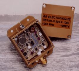
Fig. 3-6 : phase noise under previous vibration profile 4- OTHER CHARACTERISTICS The oscillator is enclosed in a milled aluminium case (fig. 4-1) with a coating treatment resistant to salt fog. The total consumption is ~50mA under a 15V supply. Fig. 4-1 : case 3447 FM 13 5- CONCLUSION A.R.Electronique has designed a high performance and reliability UHF oscillator especially developed for severe avionic environmental conditions. This relatively low cost UHF oscillator family has been introduced in other fields than radar applications, like : - high stability UHF source lockable on external standard like cesium or GPS for broadcast applications, - low phase noise UHF reference for satellite base station. This work was supported by ANVAR. REFERENCES - Low cost frequency multiplier using surface mount pin diodes AN 1054 Hewlett Packard. - Filler R.L.and Vig J.R. The acceleration sensitivity of quartz crystal oscillators : Review proc. 41 ST ASFC (1987), pp 398-408. - Frerking M.E. Crystal oscillator design and temperature compensation Van Nostrand Reinhold Company (1978) - Tuladhar K.K. High frequency quartz crystal oscillators for avionic systems. |